Adjusting the total station
All total stations require regular and routine checks and adjustments to deliver optimum results. All Trimble total stations allow fully accurate measurements to be made with a single pointing to a target. To achieve those results, the total station stores its current adjustment values internally, and then corrects all measured data accordingly. For accurate measurements to be made, the current adjustment values need to be determined and stored in memory. Total station adjustments are required because of the optical-mechanical design of the instrument. The following conditions can move the optics and mechanics out of adjustment:
- Shippingandhandling
- Bumpsandknocks
- Temperatureandpressurechanges
- Storageconditions
- Generalwearandtearofmechanicals
To start the calibration:
- From the Home menu, tap Total Station / Total Station Calibration.Compensator Calibration

CAUTION – You must perform this calibration before the HA VA Collimation and Tracker Collimation. The compensator does not need to be calibrated every time the other collimations are performed, but if the Compensator Calibration is performed, you should immediately perform the HA VA Collimation and Tracker Collimation. Performing the Compensator Calibration negates the validity of the values of the errors found from previous HA VA Collimations and Tracker Collimations.
The SPS family of motorized total stations is all equipped with a dual-axis compensator. The compensator is active when the total station is switched on. You should periodically calibrate the compensator to adjust for any minor changes in the total station caused by normal wear and tear, as well as shipping or temperature variations. It is extremely important to perform this calibration when you are working within a very tight tolerance range. You should also perform this calibration whenever the highest accuracies are needed.
- Tap Start to initiate the instrument Level Compensator Calibration:
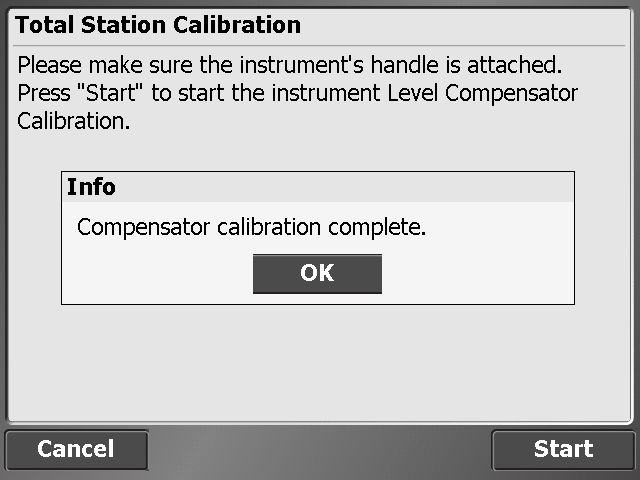
- Tap OK.HA VA Collimation test
You should perform this test to a target that can be easily bisected with both the horizontal and vertical cross-hair, placed at a location at least 100 m (328 feet) from the total station, and at approximately the same elevation as the total station telescope. The target can be any object including a road sign, window frame, or an adhesive prism target. The test involves taking a series of HA VA measurements to the target in both instrument faces, to generate a mean or averaged pointing in face 1 and face 2, from which the difference between face 1 and face 2 readings can be determined. The difference between the two face readings is known as the collimation error. In the horizontal axis, the collimation error has little effect on measurements. However in the vertical axis, if not corrected for, the collimation error will result in erroneous elevation values for all measured points.
- Enter the number of measurements, aim at the target and then tap Measure:
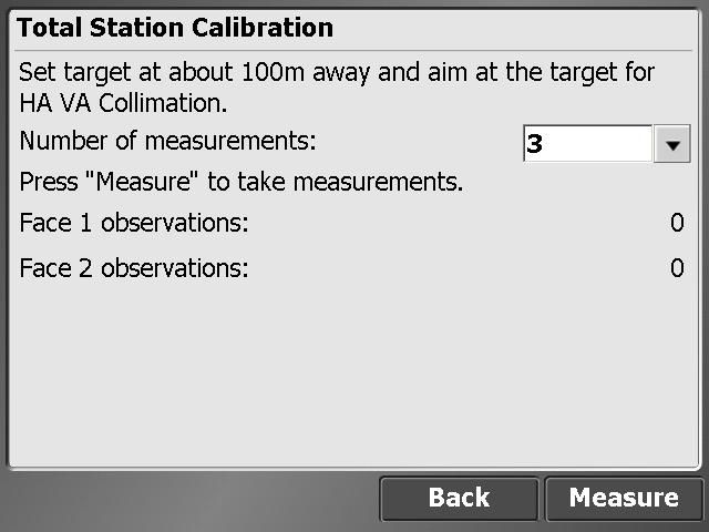
The collimation test computes the collimation error, stores the error inside the total station and then corrects all subsequent measurements for that error before displaying them on the screen or storing them in memory.
- Tap Next.Tracker Collimation test
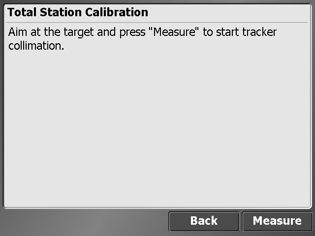
You should perform this test towards a prism or active target set up at a distance of around 100 m and at approximately the same elevation as the total station telescope. Ideally, perform the test at the approximate range that subsequent measurements will be made.
The test involves the total station locking onto and measuring an average position over a period of time in both faces to determine any misalignment of the tracker in relationship to the telescope cross-hair. If not corrected for, this error results in erroneous position determination in both horizontal and vertical axes, and also between measurements made with and without Autolock technology. Once measured, the error is stored in the total station, and is used to correct all subsequently measured positions. - Aim at the target and tap Measure:
NOTE – There can be two reasons for significant change between old and new values: (1) The total station has received a knock or bump in transit that may need a service correction, or (2) there has been an observation error.
If you suspect an observation error, repeat the process. If the values are repeated, you may want to contact an authorized Trimble Service Center for advice. When the values exceed a certain level, you will be advised to send the total station to an approved Trimble Service Center for recalibration.
NOTE – The values displayed when new will be close to zero, but over time these are expected to change. Non-zero values are no cause for concern; however, sudden large changes should be cause for concern because they indicate misuse, abuse, or transportation problems. For full details of the instrumentation errors, refer to your instrument manual.
- Tap Finish.
Measure Control Network
The SCS900 software includes the Measure Control Network function, which enables you to configure and measure rounds of angles to different control points of a network or traverse. When you measure at least two rounds to a control point, the software will calculate the standard deviation for each foresight and backsight target (accuracy) and the standard deviation of the mean (precision). This enables you to evaluate the quality of the measurements in the field.
To use this function, you must purchase and install the Advanced Measurement module. When connected to an SPS instrument, the System Setup menu contains a new option called Measure Control Network. To adjust a traverse or control point network measured with this feature, you will require the Total Station Processing module for Business Center – HCE. The SCS900 software exports the RAW data to a DC file, which is then imported into the Business Center – HCE.
Measuring rounds of angles
To start the network measurement:
- Open a site and work order that contains your existing control points and connect the controller to an instrument.Optionally, you can perform an instrument setup before starting the network measurement. This enables you, during the configuration of the network measurement, to check the point locations to verify if the prisms were set up over the correct control point.
- Tap Home / Total Station / Station Setup / Measure Control Network.
- Use the following screen to configure the measurements for a control point: